Linear Motor / Flexure Carriage
Introduction
This design originated from a requirement to move some optics in a highly linear manner (without pitch or yaw) with great reliability in a compact space. The assembly comprises a compact linear motor to provide motive force and, built co-axially around it, a double-compound flexure system to provide the motion. Neither the flexure concept or the linear motor is novel: my project required me to select a motor and a motion and then to design and test a combined system.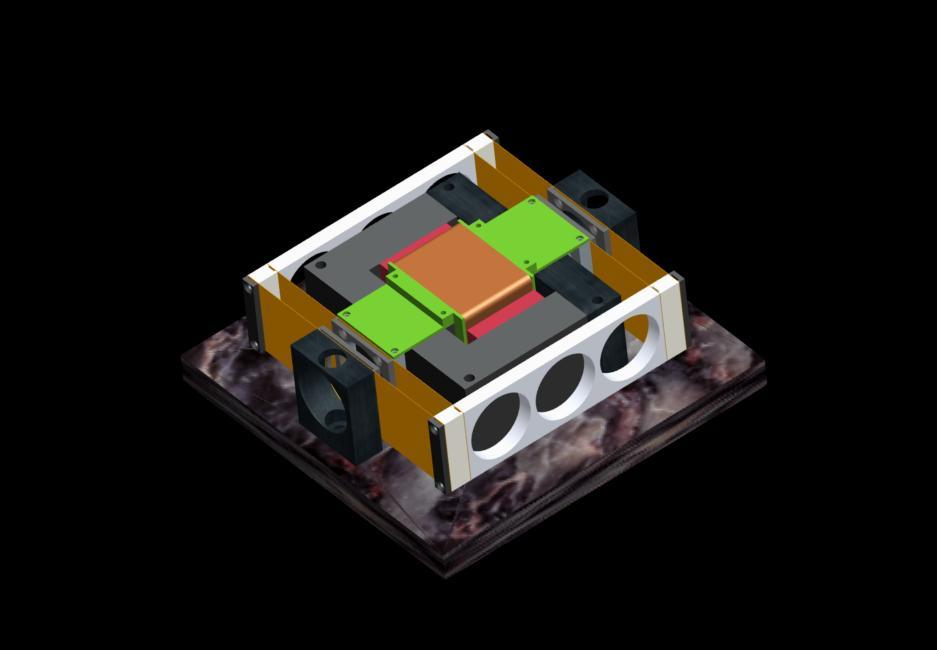
Flexures offer a nice way to avoid moving / rubbing parts and bearings, all of which usually spell trouble from wear. They operate by bending stiff, springy material (in the form of rods or, as here, thin strips) whilst certain constaints are applied (one of which being that the range of motion is usually restricted). The form of the flexure can constrain the motion to be straight, with minimal "wobble". There are no rubbing or rolling parts, and no need of lubrication. As long as the materials are carefully selected and not stressed close to their yield point, then flexures offer excellent lifetime and reliability: they have been used for precision motions in difficult situations such as vacuum and spacecraft.
The image above shows a CAD model of the completed assembly. The motor comprises a steel "E-I" core (dark grey), two high-field magnets (red) and a coil on a former (copper and green) which floats over the steel core but makes no contact with it. The flexure mechanism supports the floating coil using four flexible strips, two fixed points and two light-weight "outriggers".
Flexure Mechanism
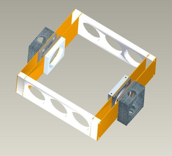 The double-compound flexure uses four strips
of a flexible, springy
material (such as beryllium copper alloy). The outer strips are
fixed
to static mounts (dark grey) which constrain each strip to sit
vertically and which prevent the centre sections from bending.
The inner strips carry at their centres mountings for the moving
carriage which impose similar constraints. The outer and
inner strips join at their ends at two "outriggers" which maintain the
strip spacing and which also ensure that the ends of the strips cannot
bend and stay vertical.
The double-compound flexure uses four strips
of a flexible, springy
material (such as beryllium copper alloy). The outer strips are
fixed
to static mounts (dark grey) which constrain each strip to sit
vertically and which prevent the centre sections from bending.
The inner strips carry at their centres mountings for the moving
carriage which impose similar constraints. The outer and
inner strips join at their ends at two "outriggers" which maintain the
strip spacing and which also ensure that the ends of the strips cannot
bend and stay vertical.If the inner mounts are moved along the axis of motion, the inner strips begin to bend so that each side adopts a very shallow "S" shape (the same shape one uses to make a saw blade "sing"). The whole strip slighly resembles a recurved bow. The bending tends to push the outriggers along slightly, and these in turn bend the outer strips which take up a similar shape. If all the strips are identical, when the centre mounts move one unit, both outriggers move half a unit. The outriggers should be light to permit teh system to me moved rapidly without inconvenient resonances.
The outriggers are connected only to the strips. As the inner and outer strips bend, the outriggers on each side tend to move inwards towards the centre of the assembly. This small motion on either side helps to constrain the motion of the centre mounts to be linear. Yaw and pitch are avoided by the length and height of the assembly and the constraints imposed by the strips (which are stiff in directions other than bending out of plane).
Linear Motor
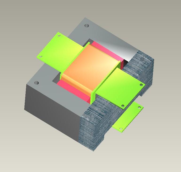
The linear motor is buill around a massive steel or soft-iron "E-I" core. A square-section coil is wound on a former that is free to move along the centre of the core (without making contact), and on two sides there are strong rare-earth magnets which provide a relatively uniform magnetic field across the coil turns. The coil former doubles as a mount for the object which has to be moved; it is supsended from the flexure assembly at the ends amd therefore moved in a linear fashion.
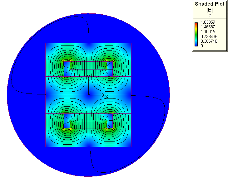 The magnetic field in the core (with no coil drive)
resembles four
loops: there is a strong field directed inward from both sides of
the
core toward the centre by the magnets (which are extremely fierce!).
This field then circulates back around the outer parts of the
core.
The importantaspects are the strength and the uniformity of the
field
in the space where the coil windings sit. The magnet thickness
and
material grade must be selected quite carefully!
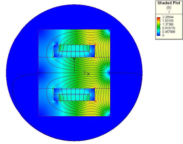
As the coil current is increased, a "solenoidal" field is generated along the central beam of the magnetic core: this field adds to that already present from the permanent magnets as shown in the second image. The design aims to maintain a strong field around the coil whilst preventing saturation at any point within the magnetic circuit.
The model proved to be extremely useful and accurate in predicting teh actual fields and teh non-linearities of the motor.
Conclusions and Acknowledgements
The assembly works as predicted: it moves about +/- 3 mm with a stiffness close to 2N / mm but it is not without problems. There are a few tricky resonances, although these can be damped out by using an appropriate coil driver and position servo system (the coil can act as a very efficient generator if moved!). Linearity of motion is excellent, as is resistance to yaw and pitch, but both the loading of the carriage and the assembly must be done symmetrically (preferably using a jig).I am indebted to Ralph Carter for computing the resonant modes of the system, to Phil Cunningham for patiently teaching me to drive Pro Engineer and to Paul Styles who is a magician when it comes to assembling things. His assembly looked better than the CAD model!